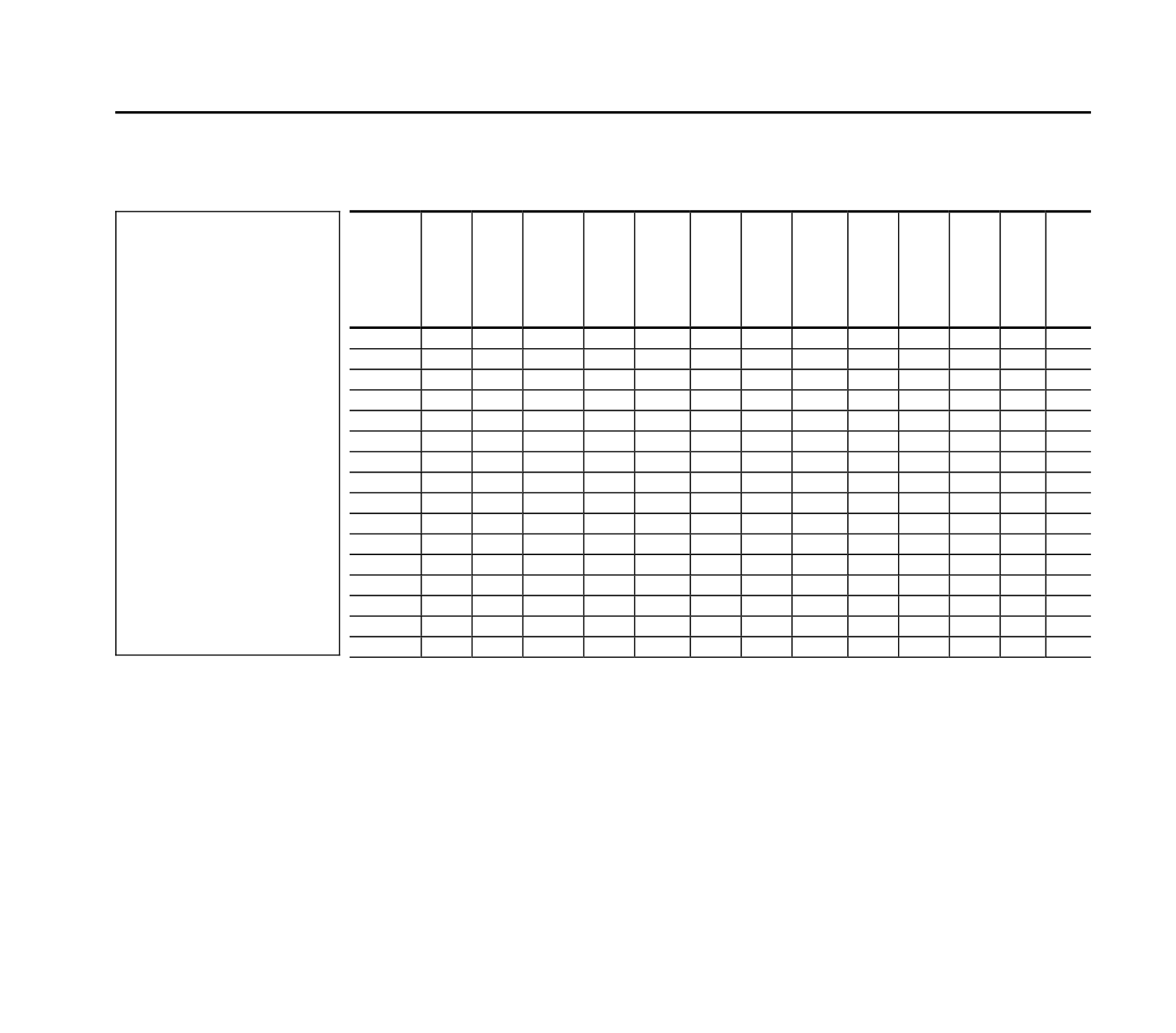
DSF-450 12,5 2,5 12,8 4,0 35
50 25 24
47 2926 0 A AP
DSF-455 12,5 2,5 12,8 4,25 35
51 25 24
49 2926 90 B AP
DSF-460 14,5 2,5 14,8 6
40
60 25 26
80 2978 0 A AP
DSF-465 14,5 2,5 14,8 6,25 40
61 25 26
83 2978 90 B AP
DSF-500 15,5 3,2 15,8 4
40
60 28 26
43 5839 0 A AR
DSF-505 15,5 3,2 15,8 4,25 40
61 28 26
45 5839 90 B AR
DSF-510 18,2 3,2 18,8 6
45
72 28 28
75 5964 0 A AR
DSF-515 18,2 3,2 18,8 6,25 45
74 28 28
78 5964 90 B AR
DSF-550 20 3,6 20,6 4
45
66 30 28
48 8354 0 A AS
DSF-555 20 3,6 20,6 4,25 45
67 30 28
51 8354 90 B AS
DSF-560 21 3,6 21,8 6
50
80 30 30
76 8409 0 A AS
DSF-565 21 3,6 21,8 6,25 50
82 30 30
79 8409 90 B AS
DSF-600 26 4
26,6 4
50
76 36 30
55 11497 0 A AT
DSF-605 26 4
26,6 4,25 50
78 36 30
58 11497 90 B AT
DSF-610 32 4
33,1 6
60
92 36 32
102 11741 0 A AT
DSF-615 32 4
33,1 6,25 60
94 36 32
106 11741 90 B AT
Stainless double torsion
spring material no. 1.4310
(EN 10270-3, A301,
BS 301S21) available with 2
leg positions, 0° and 90 °.
d =
wire diameter
Di
=
inner diameter
Dd
=
mandrel diameter
L1
=
total length
L2
=
inside length of
connecting bar
L3
=
measurement from mid-coil to
outer edge of connecting bar
a
n
=
maximum angle of rotation
Mn
=
maximum torsional moment
a
s
=
angle between leg and
connecting bar
R =
leverage
To calculate the maximum load (Fn) which
a spring can take the maximum
torsional moment (Mn) must be divided by
the lenght of leverage (R). Fn = Mn/R.
(Leverage = Distance from center of spring
body to the point of incoming strenght)
413
Double torsion spring
Stainless steel no. 1.4310 (A301, BS 301S21)
article
no.
Dd
max.
man-
drel
d
wire
dia-
meter
Di
inner
coil
dia-
meter
n
num-
ber
of
coils
Ls
leg
lengths
L1
width
L2
width
of con-
necting
bar
L3
distance
from cen-
tral coil to
connec-
ting bar
a
n
max.
angle
of
rotation
Mn
max.
tor-
sional
mo-
ment
a
s
angle
between
leg and
conecting
bar
form
pic.
price
group


