342
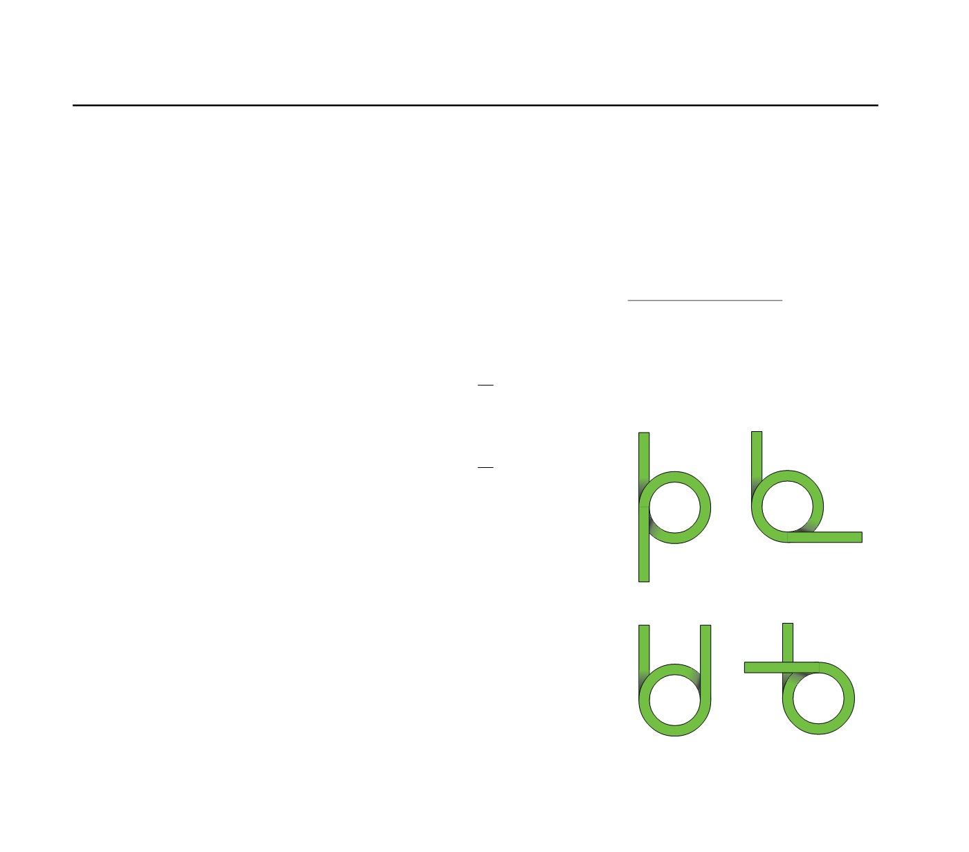
A
B
C
D
Torsion springs
Torsion springs are manufactured from stainless
steel spring wire material no. 1.4310 in compli-
ance with EN 10270 part 3 (A301 / BS 301S21).
The tolerances of the wire diameters comply with
EN 10270.
Torsion springs are available from stock with
either right (clockwise) or left (anti-clockwise)
hand coiling. An catalogue number ending with
the letter "R" in the tables indicates a right-hand
coiled spring, and a number ending with the letter
"L" indicates a left-hand coiled spring.
Torsion springs should always be loaded in
the direction of coiling. It is therefore
necessary to state the direction of coiling by
using the corresponding catalogue number
for each spring. Both coiling directions are
shown in the diagrams for guidance.
The spring bodies are coiled without pitch.
The legs extend at a tangent from the spring body.
Standard legs are straight, we an also supply
torsion springs with any form of leg for an
extra charge.
Torsion springs are usually operated in conjunction
with a mandrel which holds the spring in position.
We have provided a range of possible mandrel
diameters for each respective torsion spring, as
the spring body tends to contract when bending if
the mandrel is too large, and to tilt if the mandrel is
too small. The smallest possible mandrel
diameter in the table is represented by "Ddmin",
and the largest by "Ddmax".
We have stated the maxium possible torque in
the column "Mn", as the length of leverage is
different in every application.
The maximum possible spring load can be
determined by dividing "Mn" by leverage "RH":
To calculate the load at a particular angle " x"
the following formular must be used:
Here, n is the largest possible rotation angle
given in the table.
Torsion springs are available in stock with leg
positions 0 degrees (A), 90 degrees (B), 180
degrees (C), and 270 degrees (D).
The springs in the diagrams are all right-hand
coilded.
The spring manufacturers require a production
compensation, in order to retain the default
parameters (DIN 2194). Normally our springs are
compensated through the spring's unloaded leg
position ( ).
The calculation of torsion springs is carried out
according to EN specification 13906 section 3.
DIN 2194 Grade 2 is taken as the basic standard
for the tolerances.
Please contact our service department in
Metzingen and Cunewalde if you have any
questions about torsion springs.
Metzingen
Phone 0049 (0)7123 960-119, Fax -195,
Cunewalde
Phone 0049 (0)35877 227-11, Fax -14
Material
Design
Legs
Loads
Leg position
Production compensation
Calculation
Mandrel
Fn =
Mn
RH
Fx = · x
Fn
n


